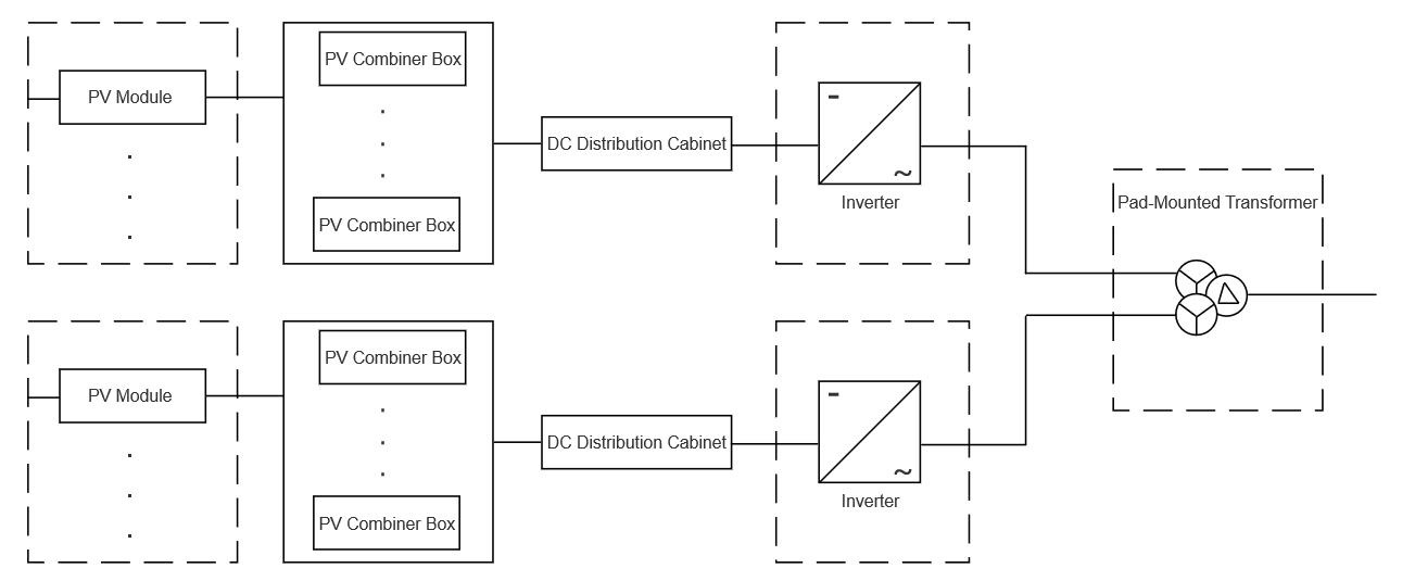
To effectively analyze the fault conditions of the pad - mounted transformer, this paper selects a double - secondary - winding pad - mounted transformer (ZGS11 - Z.T - 1000/38.5), which can be connected to 2 centralized inverters. The structure of its power generation unit is shown in Figure 1. This pad - mounted transformer adopts a three - phase three - limb structure design, with 2 windings on the low - voltage side. The overall structure is divided into three major parts: the high - voltage chamber, the low - voltage chamber, and the oil tank. In actual operation, common faults of the pad - mounted transformer include low - voltage winding grounding faults, high - voltage side open - circuit faults, and high - and low - voltage side short - circuit faults. A detailed analysis will be carried out below.
1 Typical Faults of Pad - Mounted Transformers in Photovoltaic Power Stations
1.1 Low - Voltage Winding Ground Faults
Some photovoltaic pad - mounted transformers lack a neutral - point lead. A single - phase ground fault on the low - voltage side damages insulation, with fault manifestations varying by the centralized inverter’s state.
In low - light conditions, the power - generation unit stops, and the inverter disconnects from the grid, drawing power via the transformer. A ground fault here causes the inverter (still at normal voltage) to run, but rising phase voltage damages low - voltage - side insulation long - term, possibly leading to multi - point grounding.
In sufficient light, the inverter switches to grid - connected mode. Its ungrounded neutral makes single - phase ground faults hard to detect—no ground current, unchanged line voltage. The control system, monitoring line voltage, misses the anomaly. The inverter runs but with reduced efficiency, hurting photovoltaic benefits.
1.2 High - Voltage Side Open - Circuit Faults
Open - circuit faults split into high - voltage lead and winding disconnection. A high - voltage lead disconnection trips the inverter and shuts down the generator set. Testing reveals abnormal noises, smells, and infinite resistance in the fault - phase winding (normal for others), indicating the fault.
For high - voltage winding disconnection, DC resistance is twice the normal inter - phase value (not infinite). On the high - voltage side, fault and adjacent phases’ line voltage drops to 50% of rated; on the low - voltage side, the corresponding phase’s line voltage falls (not to zero, due to induced voltage).
1.3 High - and Low - Voltage Side Short - Circuit Faults
Inter - phase short - circuit faults often occur, tripping the corresponding circuit breaker and causing noises, oil spraying, and smells.
To handle faults: first, grasp the situation from protection actions, then move the transformer to maintenance, take safety measures, and disassemble the unit to check. Initial faults may be inter - phase; if worsening, winding damage and core replacement follow.
An actual fault started as a low - voltage inter - phase short circuit, leading to high - low winding breakdown under impulse discharge. This caused severe discharge, core damage, oil tank issues. The root cause was inherent insulation weaknesses.
2 Fault Prevention for Pad - Mounted Transformers in Photovoltaic Power Stations
2.1 Insulation Monitoring Devices
The monitored transformer uses a three - phase three - wire star connection. Single - phase ground faults (no neutral point) barely change line voltage, making detection hard and risking fault worsening. Add an insulation monitoring device to alarm and enable timely faulty unit disassembly. Use a neutral - point - connected inverter (preferably yyn11 type) for better ground fault handling.
2.2 Routine Insulation Monitoring
Strict regular inspections (focus on insulation) detect defects early, reducing internal equipment failures. Increase pad - mounted transformer insulation monitoring frequency in operation and maintenance.
2.3 Oil Sample Testing
Internal insulation defects cause failures. Regular oil sample testing catches heat/discharge - related component changes during deterioration. Strengthen oil temperature monitoring and testing to avoid overheating - induced faults.
2.4 Technical Selection in Construction
Ensure long - term safety by doing good site selection, electrical design, and equipment selection in the construction phase—guaranteeing product quality and compliance with station design.
3 Conclusion
This paper analyzes common ground, disconnection, and short - circuit faults of a typical pad - mounted transformer in photovoltaic stations. To avoid faults, strengthen routine insulation monitoring, emphasize oil tank testing, and add insulation devices when possible—ensuring safe operation.