General Rules for GIS Grounding and bonding
In most Gas - Insulated Switchgears (GIS), there are two grounding grids:
- The station grounding grid, which is analogous to that in a typical Air - Insulated Switchgear (AIS) installation.
- The GIS grounding mesh, a closely - spaced grounding grid embedded in the concrete slab where the GIS is installed.
Typical rules for GIS grounding and bonding are as follows:
- All grounding conductors should be kept as short as feasible.
- The grounding mesh and its interconnections must be able to carry the system's fault currents.
- All exposed grounding conductors should be safeguarded against mechanical damage.
- At all discontinuities within the GIS, appropriate grounding and bonding techniques, such as using multiple conductors or voltage limiters, must be employed.
- Ensure that all metallic building components, GIS support structures, and GIS maintenance platforms are properly grounded.
- Reinforcement steel in the building floor should be linked to the GIS grounding mesh to further balance ground potentials.
- All secondary cables should be shielded, with both ends of each cable shield grounded to reduce potential electromagnetic interference.
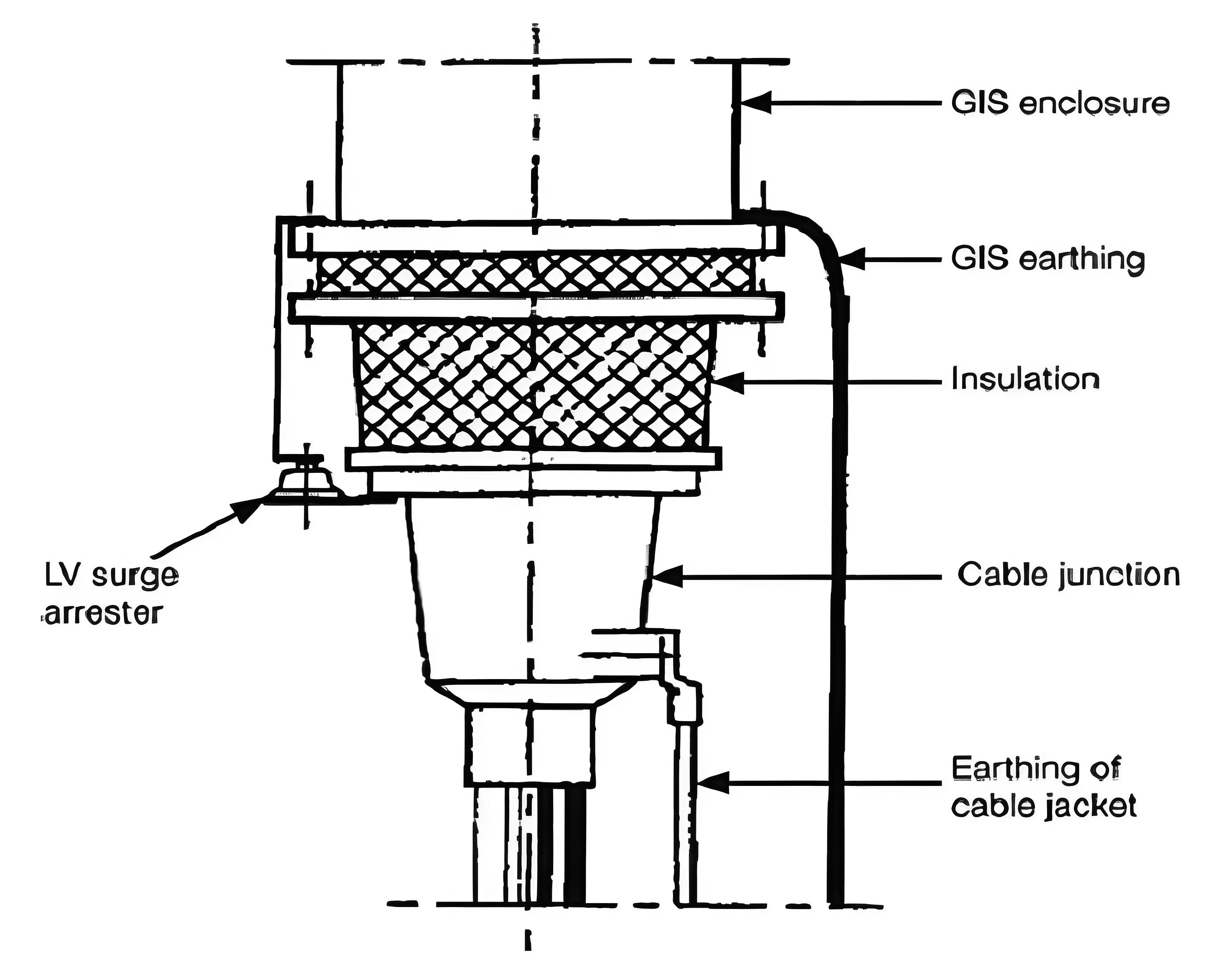
The picture depicts the insulation connection between the metal enclosure of a GIS and the metal part of the cable via nonlinear resistors.