Practice of Intelligent Switchgear Transformation in the 6kV Working Section of a Power Plant

Echo
06/11/2025
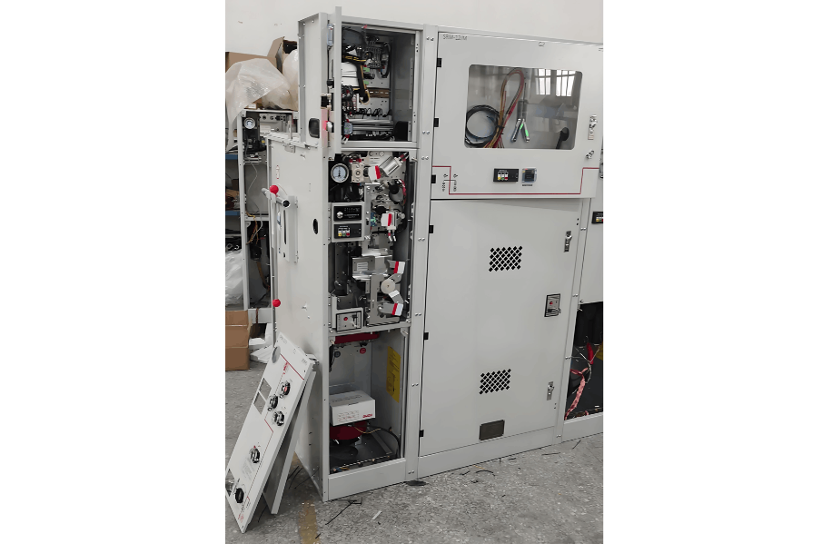
Due to the long service life and severe aging of the equipment, the switches in the 6kV working section of Unit 6 of a certain power plant have potential safety hazards such as deformed locating pins, abnormal closing positions of the earthing switches, and malfunctions of the protection devices. These hazards have threatened the stable operation of the unit, making the transformation extremely urgent. Meanwhile, considering the recent cases of electric shock casualties involving medium-voltage switches, we have decided to adopt intelligent switchgear. We remotely implant the intelligent control program into the existing ECMS, configure electric operating mechanisms, visual monitoring, and online monitoring systems to achieve one-button operation and status early warning, keeping personnel away from the equipment itself and ensuring operational safety.
1. Overall Objectives of the Intelligent Switchgear Transformation
The intelligent switchgear can remotely monitor the electrical parameters of traditional equipment through control, measurement, and communication devices. It uses electric mechanisms to complete the racking in/out of circuit breakers and the opening/closing of earthing switches, achieving intelligent operation. This transformation focuses on two major functions: "operation automation" and "status monitoring". It also integrates the existing online harmonic monitoring devices and motor insulation online monitoring devices to enhance the equipment status perception capability. For common problems such as overheating of cable terminals, jamming of mechanisms, abnormal switch characteristics, and low motor insulation, early warning and diagnosis are realized based on online monitoring data, providing support for the reliable operation of the equipment.
2. Transformation Scheme of the Intelligent Switchgear
(1) Realization of Operation Automation
(1) Realization of Operation Automation
We remotely implant the intelligent control program into the ECMS. Considering that the existing MRC units of ABB only support hard wiring, to reduce the cost of cable laying and additional measurement and control devices, we use the Wislink2000 industrial switch in the ECMS to communicate with the WDZ - 5200 series integrated protection devices of the same manufacturer in the switchgear through RS485. Then, the protection devices are connected to the MRC units via hard wiring. Finally, the electric operation functions of circuit breakers/contactors and earthing switches are realized, simplifying the control link and improving operation efficiency.

(2) Status Monitoring and Operation & Maintenance Optimization
On the status monitoring side, intelligent sensing devices for online temperature monitoring and circuit breaker mechanical characteristic monitoring are configured, and online harmonic monitoring devices and online insulation monitoring devices are integrated. Relying on the local ABB MyRemoteCare system, the health status of the equipment is evaluated in real time, and the probability of equipment failure is predicted. Through this method, the equipment operation and maintenance are promoted to transform from the "preventive maintenance" mode to the "proactive predictive management" mode, optimizing the operation and maintenance mode, reducing the probability of equipment failures, and ensuring the long-term stable operation of the unit.
3. Description of Operation Automation Functions
(1) Full Electric Drive Protection Mechanism
(1) Full Electric Drive Protection Mechanism
The switch is equipped with a professional motor drive protection device. When abnormal working conditions such as jamming occur, the motor output current increases, triggering the protection program to cut off the motor power, lock the electric operation, and activate the protection indicator light with a fault signal to avoid irreversible mechanical damage.
For the electric operation of circuit breaker/contactor handcart and earthing switch, the design is as follows:
- Handcart Electric Switching: A drive motor is added to the handcart chassis to tow the handcart body for switching between the working position and the test position. An intelligent monitoring unit with anti-stall function is configured to effectively avoid misjudgment of handcart mechanical faults; when a motor failure occurs, it automatically protects the motor and drive mechanism, with the fault indicator light on and an alarm signal issued.
- Earthing Switch Interlocking: The electric operation of the earthing switch is interlocked with the circuit breaker/contactor handcart. The full electric operation mode of the handcart and earthing switch significantly improves operation efficiency and ensures operator safety—operators no longer need to enter the switch room for on-site operation, reducing load switching waiting time and avoiding personal injury from operation failures.
(2) Programmed Operation Logic
- One-button Sequential Operation: When receiving a circuit breaker closing command, the system automatically opens the earthing switch first, then electrically racks in the circuit breaker handcart; after the handcart is in place, the closing operation can be executed from the DCS (the opening operation is reversed). It supports remote switching of switchgear among earthing maintenance, cold standby, hot standby, and operation states to achieve sequential control.
- Operation Mode Requirements: Equipped with electric operation devices for circuit breakers/contactors and earthing switches, as well as full-process visual monitoring devices, to achieve remote visualization of circuit breakers and earthing switches for intuitive operation status tracking and daily business management. It meets safety operation and maintenance requirements, enabling remote or local centralized control; manual and electric operations can be freely switched and interlocked to ensure operation safety.
4. Description of Condition Monitoring Functions
(1) Real-time Diagnosis Based on Load Changes
(1) Real-time Diagnosis Based on Load Changes
To timely identify potential equipment defects and hidden hazards, issue early warnings, prevent problem escalation, and reduce the probability of unexpected power outages, wireless radio frequency technology is adopted to real-time collect and monitor parameters such as temperature rise of switch contacts/lead terminals and switch dynamic characteristic asynchrony. Meanwhile, the operation records collected by the online monitoring and diagnosis system during long-term operation provide reliable basis for equipment health assessment.
(2) Online Temperature Monitoring Scheme for Switchgear
- Temperature Measurement Layout: 6 points for circuit breaker moving contacts (upper and lower contacts) and 3 points for the cable side; 3 points for the upper busbar branch side, 3 points for the lower contact arm, and 3 points for the cable side of the contactor.
- Technical Features: The circuit breaker temperature measurement adopts a built-in design to avoid exposure on the contact arm or finger; all temperature measurement modules use self-powered wireless radio frequency communication for battery-free operation. When circuit breakers/contactors are replaced, the online temperature monitoring device can quickly identify new equipment and automatically pair with it to ensure the matching of the monitored switchgear and circuit breaker, which is realized by automatically adapting to the cabinet detection unit without manual intervention (i.e., without replacing temperature measurement elements).
(3) Video Remote Monitoring Logic
Video monitoring equipment is configured inside the switchgear to remotely transmit monitoring images, allowing users to real-time view equipment operation status through the host computer and ensure stable equipment operation.
- Online Video Technical Requirements: When an equipment operation is selected in the operation system (ECMS), the visual system automatically switches to the video of the operated equipment after the command is issued, recording the entire operation process for direct observation and judgment on whether the operation process and status of circuit breakers/contactors and earthing switches are in place and the contact is good, meeting remote inspection requirements. The camera is directly installed in the high-voltage compartment, verified for switchgear insulation performance and electromagnetic compatibility, and connected to the video monitoring system via Ethernet to monitor the status of circuit breaker/contactor handcarts, switchgear shutters, and earthing switches. The video terminal can call the monitoring images of corresponding parts for remote inspection without on-site personnel. When remotely operating switchgear, the camera automatically feeds back video monitoring images through motion detection, enabling operators to online monitor the electric operation process and status via the host computer, eliminating the tedious on-site confirmation.
(4) Principle of Online Harmonic Monitoring
When electrical equipment operates under abnormal or degraded conditions, it generates high-order harmonics of different frequencies. The equipment degradation degree is determined through the calculation process of "relative harmonic content → indicator value → standard value": first, the relative harmonic content of each order of current harmonics is divided by the total harmonic distortion of current harmonics of the predetermined order to obtain the indicator value; then, the harmonic function of each order formed by the indicator value is multiplied by the calculated value for each order's diagnosis derived from the relative harmonic content of each order to obtain the standard value; finally, the indicator value is compared with the standard value to determine the equipment degradation degree.
- System Composition: Consists of a data acquisition system (responsible for real-time online collection of motor high-order harmonic data) and a data analysis system (relies on analysis software for real-time analysis of high-order harmonic data and fault early warning). The entire system uses non-contact high-order harmonic acquisition sensors to online collect operation equipment data, and determines the equipment degradation degree through comprehensive analysis of high-order harmonic components and their content rates, providing a basis for maintenance.
(5) Practice of Motor Insulation Online Monitoring
Insulation testing is required to determine the insulation status of high-voltage motors before power transmission and during daily standby, which is a key link in equipment operation and maintenance and an effective means to ensure system safety. For the regular insulation testing needs of open motors (such as circulating water pump motors and feed water pump motors) and long-term standby motors in the unit, insulation online monitoring devices have been equipped early. The DC high-voltage injection method is used for insulation measurement of cables or motor windings; when the line is powered off, the insulation monitoring device automatically starts insulation monitoring of the feeder circuit, real-timely displaying the insulation values of standby equipment to facilitate daily operation and maintenance.
5. Discussion on Improvement Directions
(1) Centralized Management of Control Power
(1) Centralized Management of Control Power
Introduce line-controlled intelligent miniature circuit breakers accessible to DCS, ECMS, or NCS to achieve centralized control of control power. Cooperate with main equipment racking in/out and switching operations to complete full-process sequential control, deeply integrating into operation management and optimization.
(2) Improvement of Insulation Monitoring System
Add motor insulation online monitoring terminals (supporting residual current monitoring of motor circuits when the motor is powered on) to improve the full-process monitoring of insulation performance for standby and operating equipment:
- Reduce regular insulation testing workload and operation risks;
- Collaborate with harmonic monitoring and MRC to provide a basis for equipment condition-based maintenance;
- Insulation data can communicate with the background via RS 485 signals or output insulation/leakage current early warning/alarm signals via hard wiring for automatic switching interlocking of electric heaters and motors.
(3) System Integration Optimization
Connect all operation processes of intelligent switches to the host DCS to replace independent ECMS, reducing investment costs, facilitating centralized DCS control and management of equipment, optimizing and centralizing inspection work, and reducing human resources.
6. Conclusion
6kV switchgear plays a key role in the plant power system, with operation monitoring, power switching, insulation testing, and maintenance being indispensable in daily operation and maintenance. For smart power plant construction, 6kV switchgear must focus on ensuring personnel safety, equipment reliable operation, labor intensity reduction, and condition-based maintenance, continuously optimizing the existing operation and maintenance mode to achieve safer, more efficient, and economical operation.
As an expert in the application and trends of electrical equipment, I have a profound mastery of knowledge in circuits, power electronics, etc. I possess a comprehensive set of abilities including equipment design, fault diagnosis, and project management. I can precisely grasp the industry's pulse and lead the development of the electrical field.