No-Load Operation of Transformer
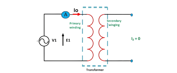
When a transformer operates under no-load conditions, its secondary winding is open-circuited, eliminating load on the secondary side and resulting in zero secondary current. The primary winding carries a small no-load current I0, comprising 2 to 10% of the rated current. This current supplies iron losses (hysteresis and eddy current losses) in the core and minimal copper losses in the primary winding.
The lag angle of I0 is determined by transformer losses, with the power factor remaining very low—ranging from 0.1 to 0.15.
No-Load Current Components and Phasor Diagram
Components of No-Load Current
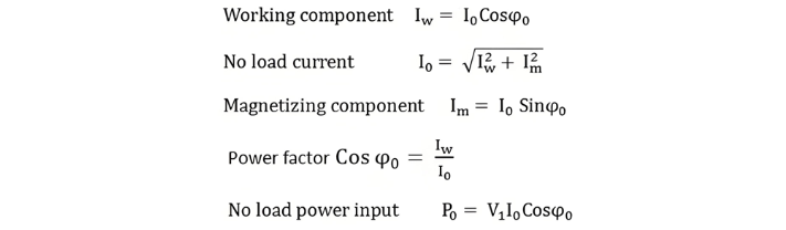
The no-load current I0 comprises two components:
Phasor Diagram Construction Steps
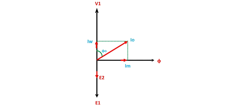
- The magnetizing component Im is in phase with the magnetic flux ϕ, as it generates the magnetizing flux.
- Induced EMFs E1 and E2 in primary/secondary windings lag the flux ϕ by 90°.
- Primary copper losses are negligible, and secondary current I2 = 0, eliminating secondary losses.
- The no-load current I0 lags V1 by angle ϕ0 (no-load power factor angle), as depicted in the phasor diagram.
- The applied voltage V1 is drawn equal and opposite to E1, as their no-load difference is negligible.
- The active component Iw is aligned in phase with V1.
- The no-load current I0 is the phasor sum of Im and Iw.
From the phasor diagram drawn above, the following conclusions are made: