What impact does rotor-stator proximity have on heat generation?
Impact of the Distance Between Rotor and Stator on Heating
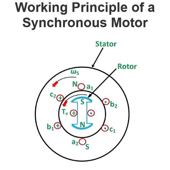
In electric motors, the distance between the rotor and stator (known as the air gap) significantly affects the motor's heating performance. The size of the air gap directly influences the motor's electromagnetic, mechanical, and thermal properties. Below are the specific impacts of the air gap on heating:
1. Impact on Electromagnetic Performance
Flux Density Changes: The size of the air gap directly affects the magnetic flux density within the motor. A smaller air gap means that magnetic flux can pass more easily, reducing magnetic reluctance and increasing flux density. A larger air gap increases magnetic reluctance, leading to a decrease in flux density.
Weakened Magnetic Field Strength: When the air gap is larger, the magnetic field strength weakens, resulting in poorer electromagnetic coupling between the rotor and stator. This reduces motor efficiency and increases energy losses, leading to more heat generation.
Increased Excitation Current: To maintain the same flux density, a larger air gap requires a higher excitation current. The increase in excitation current results in greater copper losses (I²R losses), which in turn increases heating.
2. Impact on Mechanical Performance
Increased Vibration and Noise: If the air gap is uneven or too large, it can cause misalignment between the rotor and stator, leading to increased mechanical vibration and noise. Vibration not only affects the stability of motor operation but also accelerates wear on bearings and other mechanical components, potentially causing additional heating.
Risk of Friction: If the air gap is too small, there is a risk of contact or friction between the rotor and stator, especially under high-speed operation or fluctuating loads. This friction generates significant heat and can severely damage the motor.
3. Impact on Thermal Performance
Reduced Heat Dissipation Efficiency: A larger air gap increases the thermal resistance within the motor, making it harder for heat to be conducted from the interior of the motor to the external environment. This leads to higher internal temperatures, particularly in the windings and core, accelerating the aging of insulation materials and shortening the motor's lifespan.
Localized Overheating: If the air gap is uneven, certain areas may have an excessively small gap, leading to localized magnetic flux concentration and localized overheating. This accelerates the degradation of insulation materials in those regions, increasing the risk of failure.
Increased Temperature Rise: Due to the weakened magnetic field strength and increased excitation current caused by a larger air gap, both copper losses and iron losses increase, leading to a higher overall temperature rise. Excessive temperature rise can affect motor efficiency and reliability, and may even trigger the motor's overheat protection, forcing it to shut down.
4. Impact on Efficiency and Power Factor
Reduced Efficiency: A larger air gap results in more energy losses, primarily due to increased excitation current and reduced magnetic flux density. These losses manifest as heat, lowering the motor's overall efficiency.
Decreased Power Factor: A larger air gap increases the motor's reactive power demand, leading to a lower power factor. A low power factor means the motor requires more current to produce the same output power, increasing line losses and the burden on transformers, which further exacerbates heating issues.
Summary
The distance between the rotor and stator (air gap) has a significant impact on the heating of an electric motor. A smaller air gap improves magnetic flux density and electromagnetic coupling efficiency, reduces excitation current and energy losses, and thus lowers heating. However, an air gap that is too small can lead to mechanical friction and localized overheating risks. A larger air gap weakens the magnetic field strength, increases excitation current and energy losses, leading to more heat generation, and reduces motor efficiency and power factor. Therefore, properly designing and controlling the air gap size is crucial for ensuring efficient and reliable motor operation and extending its lifespan.
The Electricity Encyclopedia is dedicated to accelerating the dissemination and application of electricity knowledge and adding impetus to the development and innovation of the electricity industry.


