Brushless DC Motor Drives
Definition
A brushless DC motor drive is defined as a self - controlled variable frequency drive that utilizes a sinusoidal Permanent Magnet Alternating Current (PMAC) motor. This type of drive offers several notable advantages. Practically maintenance - free, it boasts an extended lifespan, making it a reliable choice for various applications. Additionally, it features low rotational inertia, minimal friction, and operates with low - frequency characteristics. Moreover, it generates minimal radio frequency interference and noise, ensuring smooth and quiet operation. However, it is not without drawbacks; the primary limitations are its relatively high cost and low starting torque.
Applications
Brushless DC motor drives find extensive use across a wide range of industries and devices. In the realm of consumer electronics, they are employed in record players, tape drives for recorders, and spindle drives in computer hard disks. They also serve as low - power drives in computer peripheral instruments and control systems. Beyond consumer electronics, their applications extend to the aerospace industry, where reliability and low - noise operation are crucial. In the biomedical field, their precision and clean operation make them suitable for various medical devices. Additionally, they are commonly used to drive cooling fans, providing efficient and quiet ventilation in numerous systems.
Motor Structure
The figure below illustrates the cross - section of a three - phase, two - pole trapezoidal PMAC motor, which is a key component of the brushless DC motor drive. The motor features a permanent magnet rotor with a wide pole arc, which contributes to its efficient operation. The stator is equipped with three - pole windings, each displaced by 120 degrees from one another. This specific winding configuration ensures balanced electrical operation and smooth torque production. Each phase winding spans 60 degrees on either side, optimizing the magnetic field interaction within the motor and enabling precise control over its speed and performance.
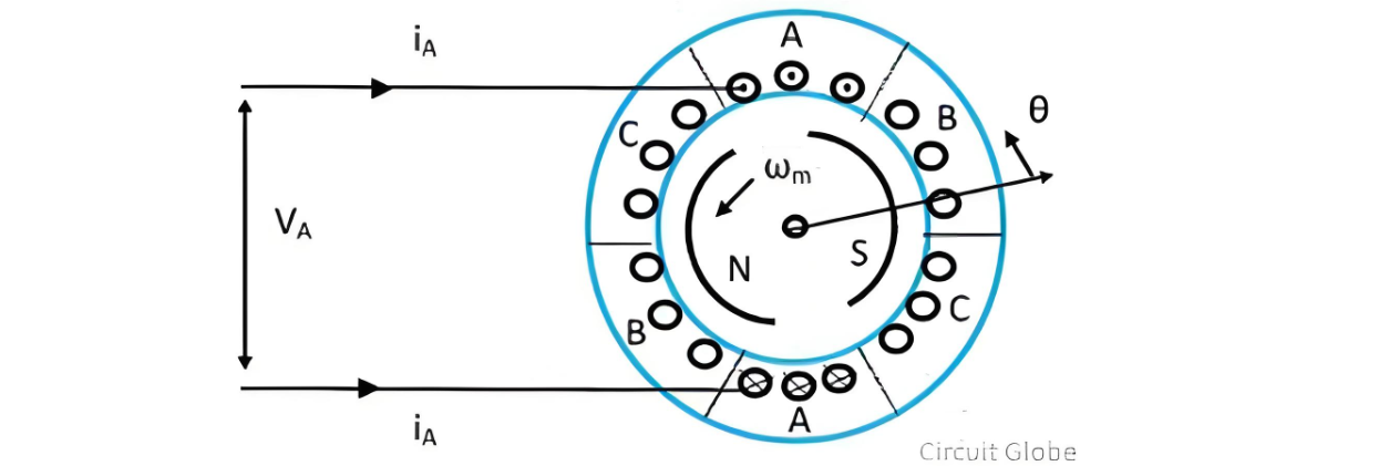
The voltages induced in the three phases of the motor are depicted in the figure below. The generation of a trapezoidal waveform can be attributed to the specific interaction between the rotor and stator. When the rotor rotates in a counter - clockwise direction, during the initial 120 - degree rotation from a reference position, all the top conductors of phase A interact with the south pole of the magnetic field, while all the bottom conductors of phase A engage with the north pole.
This consistent magnetic coupling within this angular range leads to a relatively stable induced voltage, contributing to the flat top portion of the trapezoidal waveform. As the rotor continues to rotate, the changing magnetic field orientations cause the induced voltage to transition, ultimately forming the characteristic trapezoidal shape that is essential for the proper operation and control of the brushless DC motor drive.
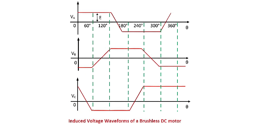
During a 120 - degree rotation of the rotor, the voltage induced in phase A remains relatively constant. Once the rotation exceeds 120 degrees, some of the top conductors of phase A begin to link with the north pole, while others continue to interact with the south pole. The same phenomenon occurs with the bottom conductors. As a result, over the subsequent 60 - degree rotation, the voltage induced in phase A linearly reverses. This pattern of voltage change is mirrored in phases B and C as well, creating a coordinated electrical behavior essential for the motor's operation.
The brushless DC motor drive system, as illustrated in the figure below, consists of a voltage - source inverter paired with a trapezoidal PMAC motor. The stator windings of the motor are configured in a star connection. The figure also depicts the characteristic phase - voltage waveform of the trapezoidal PMAC motor, which reflects the unique voltage - induction dynamics described above. This waveform is a key feature that enables the efficient control and operation of the brushless DC motor drive, facilitating smooth torque production and precise speed regulation.

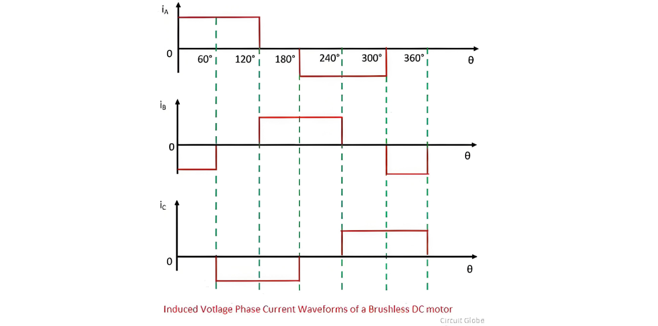
The stator windings of the brushless DC motor are supplied with current pulses. Each pulse has a duration of 120 electrical degrees and is precisely positioned within the region where the induced voltage remains constant and reaches its maximum value. Crucially, the polarity of these current pulses aligns with that of the induced voltage, ensuring a harmonious interaction between the electrical inputs and the magnetic field generated by the motor.
The air - gap flux within the motor is maintained at a steady level, and the magnitude of the induced voltage is directly proportional to the rotational speed of the rotor. This relationship is fundamental to the operation of the motor, as it allows for accurate control of the motor's performance based on the speed - dependent induced voltage, enabling efficient power transfer and smooth operation across various operating conditions.

During each 60 - degree interval of operation, current flows into one phase of the motor's stator winding and exits from another. This alternating current flow pattern is a key characteristic of the brushless DC motor's operation. As a result, the power supplied to the motor within each of these 60 - degree intervals can be expressed by the following formula, which takes into account the interaction between the voltage and current within the winding phases.

The torque developed by the motor

The torque waveform of the brushless DC motor drive is illustrated in the figure below. The magnitude of the torque generated by the motor is directly proportional to the current flowing through the DC power links. This relationship is fundamental to understanding the motor's dynamic behavior and performance characteristics.
Regenerative braking in this drive system is achieved by reversing the phase current. When the phase current is reversed, the direction of the current source Id also changes accordingly. This reversal initiates a power flow that starts from the motor, proceeds through the inverter, and ultimately returns to the DC source. During this process, the motor acts as a generator, converting the mechanical energy from the load into electrical energy, which is then fed back into the power supply. This not only helps in decelerating the motor but also allows for the recovery and reuse of energy, enhancing the overall efficiency of the system.
When the rotational speed of the drive system is reversed, the polarity of the induced voltages within the motor also flips. This change in voltage polarity triggers the regenerative braking operation, enabling the drive to convert the mechanical energy of the moving load into electrical energy that can be fed back into the power supply.
Conversely, reversing the direction of the current flowing through the motor's windings initiates the motoring operation, propelling the motor in the desired direction. The current waveforms corresponding to these distinct operating modes—regenerative braking and motoring—are clearly depicted in the figure below, providing a visual representation of the electrical behavior of the drive system under different conditions.
Types of Brushless DC Motor Drive
The brushless DC motor drive can be primarily categorized into two distinct types: the low - cost brushless DC motor drive and the single - phase brushless DC motor drive. Each type has its own unique characteristics and operational principles, which are detailed below.
Low - Cost Brushless DC Motor Drive
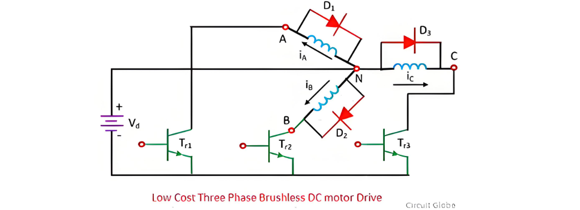
The low - cost brushless DC motor drive is designed with simplicity and affordability in mind. It features a minimalistic configuration, consisting of just three transistors and a three - diode converter. This setup restricts the drive to supplying only positive current or voltage to the three - phase motor.
During operation, the induced voltage and current play crucial roles in both the motoring and braking functions of the motor. When 120 - degree positive current pulses are delivered to the motor, it initiates a motoring action, causing the motor to rotate in a counter - clockwise direction. Conversely, when these current pulses are shifted by 60 degrees to a total of 180 degrees, the motor transitions into a braking state. This change in the timing of the current pulses effectively alters the interaction between the electrical input and the motor's magnetic field, enabling the shift from rotational motion to a braking mechanism.
Low - Cost Brushless DC Motor Drive: Current Control Mechanism
In the low - cost brushless DC motor drive, the current of phase A is precisely regulated by the thyristor Tr1 and the diode D1. When Tr1 is activated (turned on), the source voltage Vd is connected across winding A. This connection causes the rate of change of the current IA to become positive, meaning the current in phase A starts to increase. Conversely, when Tr1 is deactivated (turned off), the current iA enters a freewheeling state through diode D1. During this freewheeling process, the rate of change of iA turns negative, and the current gradually decays.
Within the 0 - 120º time period, Tr1 can be switched on and off in an alternating manner. This on - off switching strategy is employed to make the actual current IA closely track a rectangular reference current iA, ensuring that the difference between them remains within a predefined hysteresis band. This precise control helps in maintaining stable motor operation and efficient power transfer.
Single - Phase Brushless DC Motor Drive
The configuration of the single - phase brushless DC motor drive is illustrated in the figure below. For the purpose of analysis, assume that the motor is powered by a half - bridge single - phase converter, which supplies a rectangular current waveform to the motor, as depicted in the accompanying diagram. This specific current waveform plays a crucial role in determining the motor's performance characteristics and operational behavior.
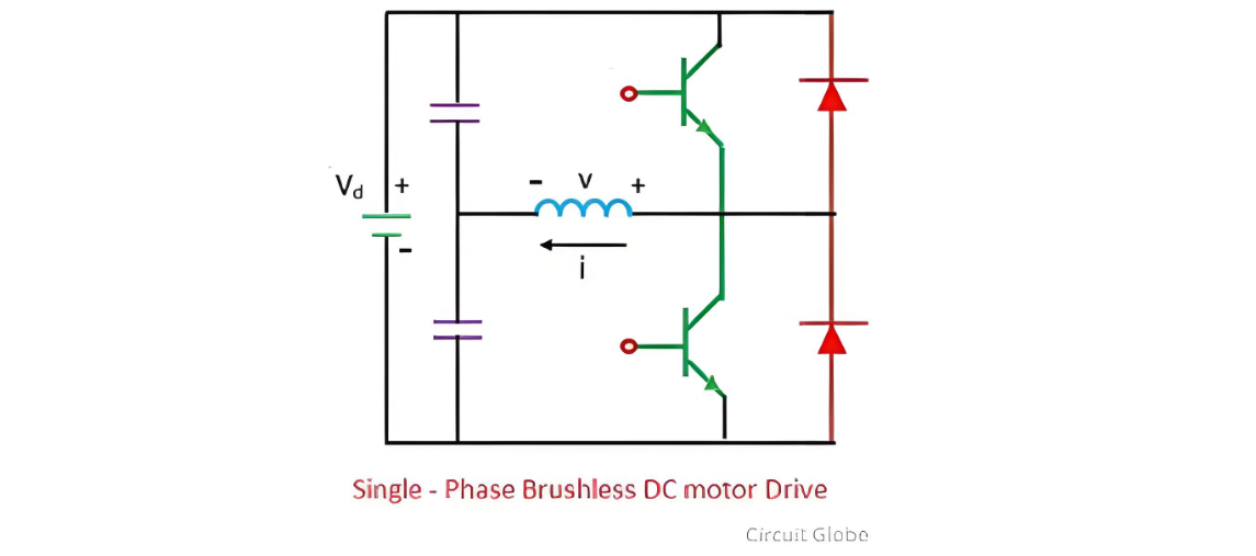
The torque generated by the motor exhibits significant fluctuations, commonly referred to as torque ripple. However, when the motor operates at high speeds, the inertia of the motor - load system acts as a natural filter. This inherent inertia smooths out the torque variations, enabling the motor to maintain a relatively uniform rotational speed despite the presence of torque ripple.
The Electricity Encyclopedia is dedicated to accelerating the dissemination and application of electricity knowledge and adding impetus to the development and innovation of the electricity industry.

