Permanent Magnet Stepper Motor
The permanent magnet stepper motor features a stator construction that closely resembles that of the single - stack variable reluctance motor. Its rotor, cylindrical in shape, is composed of permanent magnet poles made from high - retentivity steel. On the stator, the concentrating windings situated on diametrically opposite poles are connected in series, thereby forming a two - phase winding.
The alignment of the rotor poles with the stator teeth is contingent upon the excitation of the winding. For instance, the two coils AA’ are connected in series to constitute a winding for Phase A. Likewise, the two coils BB’ are connected in series to create a Phase B winding. The diagram below illustrates a 4/2 - pole permanent magnet stepper motor, providing a visual representation of its structural and winding configuration.
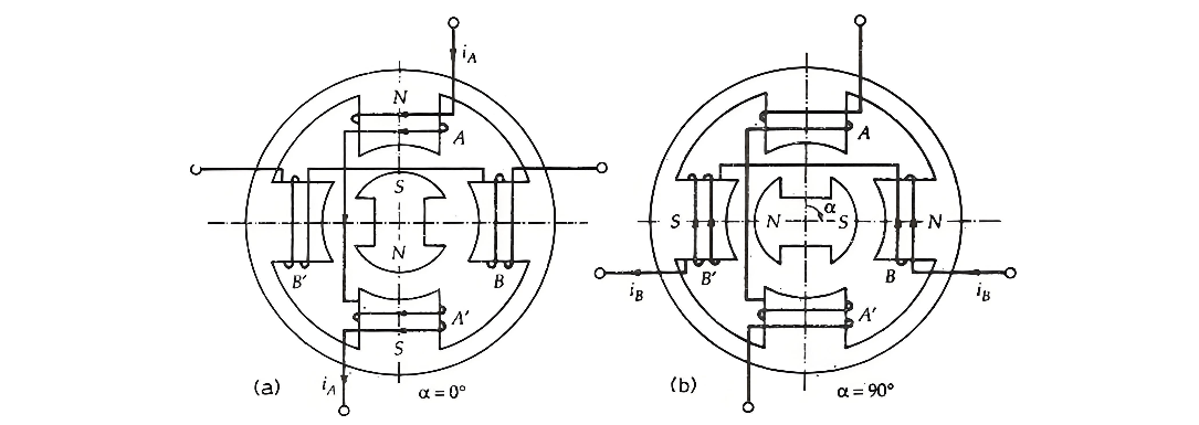
In Figure (a), the current flows from the start to the end of Phase A. The phase winding is labeled as A, and the current is denoted by iA+. This figure depicts the scenario when the phase winding is energized with the current iA+. As a result, the south pole of the rotor is attracted by Stator Phase A. Consequently, the magnetic axes of the stator and rotor align perfectly, with the angular displacement α=0∘.
Similarly, in Figure (b), the current traverses from the start to the end of Phase B. The current is indicated as iB+, and the winding is marked as B. When examining Figure (b), it can be observed that the winding of Phase A carries no current, while Phase B is excited by the current iB+. The stator pole then attracts the corresponding rotor pole, causing the rotor to rotate 90 degrees in the clockwise direction. At this stage, α=90∘.
Figure (c) illustrates a situation where the current flows from the end to the start of Phase A. This current is represented by iA−, and the winding is labeled as iA−. Notably, the current iA− has a direction opposite to that of iA+. In this case, the Phase B winding is de - energized, and the Phase A winding is activated by the current iA−. Consequently, the rotor continues to move another 90 degrees in the clockwise direction, and the angular displacement reaches α=180∘.
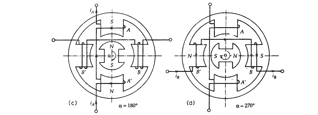
In Figure (d) above, the current flows from the end to the starting point of Phase B, denoted as iB−, and the corresponding winding is labeled B−. At this moment, Phase A is de - energized, while Phase B is excited. As a result, the rotor advances another 90 degrees, and the angular displacement α reaches 270∘.
To complete a full revolution of the rotor, achieving α=360∘, the rotor moves an additional 90 degrees when the winding of Phase B is de - energized and Phase A is excited. In a permanent magnet stepper motor, the direction of rotation is determined by the polarity of the phase current. For clockwise rotation, the sequence of phase excitation is A,B,A−,B−,A, while for counterclockwise rotation, the sequence becomes A,B−,A−,B,A.
Manufacturing a permanent magnet rotor with a large number of poles presents significant challenges. Consequently, this type of stepper motor is typically limited to large step sizes, ranging from 30∘ to 90∘. These motors have higher inertia, which results in a lower acceleration rate compared to variable reluctance stepper motors. However, they possess an advantage in that permanent magnet stepper motors can generate greater torque than variable reluctance stepper motors.
The Electricity Encyclopedia is dedicated to accelerating the dissemination and application of electricity knowledge and adding impetus to the development and innovation of the electricity industry.

