Analysis and Discussion on the Main Shaft Fault of Vacuum Circuit Breaker in EIB Mechanism

A vacuum circuit breaker is a type of circuit breaker in which both the arc - extinguishing medium and the insulating medium in the gap between the contacts after arc - extinction are vacuum. As a protection and control unit for power equipment and power - driven equipment in industrial and mining enterprises, indoor AC high - voltage vacuum circuit breakers have diverse applications and can be installed in fixed cabinets, middle - mounted cabinets, and double - layer cabinets. As a crucial electrical device among switchgear, high - voltage circuit breakers are suitable for places that require frequent operation at rated working current or multiple interruptions of short - circuit current.
This paper analyzes the problem of the switch of the EIB vacuum circuit breaker failing to open or close properly due to frequent operation. Through experiments, it is found that the tripping spring on the right side of the main shaft falling off is the cause of the circuit breaker's failure to open or close properly. An improvement measure of installing adjustment shims is proposed to ensure the normal operation of the circuit breaker, which has certain reference significance for the safety construction of enterprise production.
Structure of Vacuum Circuit Breaker
A vacuum circuit breaker mainly consists of components such as a vacuum arc - extinguishing chamber, an operating mechanism, and a support.
Vacuum Arc - Extinguishing Chamber
Also known as a vacuum switch tube, the working principle of the vacuum arc - extinguishing chamber is to utilize the excellent insulation property of the vacuum medium inside the tube, enabling the medium - and high - voltage circuit to quickly extinguish the arc and cut off the current after the power supply is cut off. Its main structures are as follows:
- Air - tight Insulation System: This is a closed container in a vacuum environment, mainly composed of an air - tight insulation cylinder, a moving - end cover plate, a fixed - end cover plate, and a stainless - steel bellows. To ensure air - tightness, strict operating processes are required for the sealing joints. In addition, materials with extremely low air permeability are needed, and the internal gas release amount also needs to be limited to a minimum value.
- Conductive System: It is mainly composed of a fixed electrode and a moving electrode. The fixed electrode includes a fixed contact, a fixed conducting rod, and a fixed arc - running surface, while the moving electrode includes a moving contact, a moving conducting rod, and a moving arc - running surface. The contact structure types can be roughly divided into the transverse magnetic field type with a spiral - groove arc - running surface, the longitudinal magnetic field type, and the cylindrical type. The operating mechanism makes the two contacts close through the movement of the moving conducting rod, thus completing the circuit connection.
- Shielding System: It is mainly composed of a shielding cylinder, a shielding cover, and other devices. Commonly used shielding covers currently include types such as the bellows shielding cover and the main shielding cover surrounding the contacts. The main shielding cover can reduce the local field strength, improve the uniformity of the internal electric field distribution of the arc - extinguishing chamber, which is conducive to the miniaturization of the vacuum arc - extinguishing chamber. At the same time, it can prevent the arc products from splashing onto the inner wall of the insulating housing during the arcing process, ensuring that the insulation effect of the housing is not affected by arc discharge. It can also absorb arc energy, condense arc products, and accelerate the recovery of the dielectric strength in the post - arc gap.
Operating Mechanism
Different types of circuit breakers use different operating mechanisms. Commonly used operating mechanisms include spring operating mechanisms, EIB spring - energy - storage operating mechanisms, CT8 spring - energy - storage operating mechanisms, CT19 spring - energy - storage operating mechanisms, CD10 electromagnetic operating mechanisms, CD17 electromagnetic operating mechanisms, etc. Among them, the spring operating mechanism has the advantages of small size, small closing current, and high reliability, and is currently widely used in switchgear of different voltage levels.
Function and Principle of Vacuum Circuit Breaker
Function and Characteristics
Under normal operating conditions, a vacuum circuit breaker that meets the technical parameter range can ensure its safe and reliable operation in the power grid of the corresponding voltage level. The mechanical life of a vacuum circuit breaker is approximately 20,000 times, and the number of full - capacity short - circuit current interruptions is 50 times. It can be operated frequently or interrupt short - circuit current multiple times within the working current range. High - voltage vacuum circuit breakers have the advantages of high reliability, all - weather operation, maintenance - free, complete functions, good interchangeability, and strong versatility, and can be applied to reclosing operations with various characteristics. Vacuum circuit breakers adopt a vertical insulation cylinder and a solid insulation structure - integrated solid - sealed pole columns, which can resist the influence of various special environments and are maintenance - free. Meanwhile, vacuum circuit breakers have multiple usage methods, which can be installed in a fixed manner, used in a withdrawable way, or installed on a frame.
Principle Introduction
When the moving and static contacts of a vacuum circuit breaker are opened while charged, a vacuum arc will be generated between the contacts. The arc raises the surface temperature of the contacts, causing metal vapor to appear on the contact surface. Based on the special shape of the contacts, when current passes through, under the action of the magnetic field it generates, the arc moves rapidly along the tangent direction of the contact surface. The metal vapor and charged particles in the arc column continuously diffuse outward, and the density of the metal vapor and charged particles keeps decreasing. When the arc naturally passes through zero, the medium between the contacts quickly recovers from a conductor to an insulator, the current is cut off, and the arc is extinguished .
Fault Cause Summary and Analysis
Analyzing the situation where the vacuum circuit breaker fails to open or fails to open completely due to frequent operation, on - site inspection reveals that the bolt at the right - hand end of the switch main shaft falls off, causing the right - hand tripping spring to drop and get stuck on the main shaft at the same time. The mechanism's tripping relies only on the tripping spring on the left side of the main shaft, resulting in the switch not opening completely. Although the probability of this fault occurring is relatively small, its occurrence may still lead to production safety accidents. Therefore, it is necessary to analyze the fault cause, eliminate potential safety hazards, and ensure safe production.
Solution and Verification Plan
The screws fixing the tripping springs on both sides of the switch main shaft of the EIB mechanism circuit breaker are ordinary screws + spring washers (see Figure 1). After years of frequent switch operation, the screw fixing the tripping spring on the right side of the main shaft falls off due to vibration, causing the right - hand tripping spring to drop and get stuck on the main shaft at the same time. The mechanism's tripping relies only on the tripping spring on the left side of the main shaft, resulting in the switch not opening completely. Through on - site investigation, it is found that there is an axial length difference of about 4mm between the spline shaft on the right side of the main shaft and the outer casing, and the end cover has deformed and sunken inward (see Figure 2). In response to this fault, that is, the circuit breaker failure caused by the tripping spring falling off due to the loosening of the end bolt of the closing and opening main shaft, to verify, a circuit breaker with a corresponding structure is then reassembled for fault simulation:
Adjust the axial length between the spline shaft on the right side of the main shaft of this simulated circuit breaker and the outer casing to create a gap of about 4mm (see Figure 3), and use a torque wrench to tighten it with a torque of 45Nm. Push it into the mechanical running - in chamber for mechanical running - in. The initial counter reading is 26 times, and the end cover shows a slight sunken phenomenon after tightening. The process is shown in Figure 4.
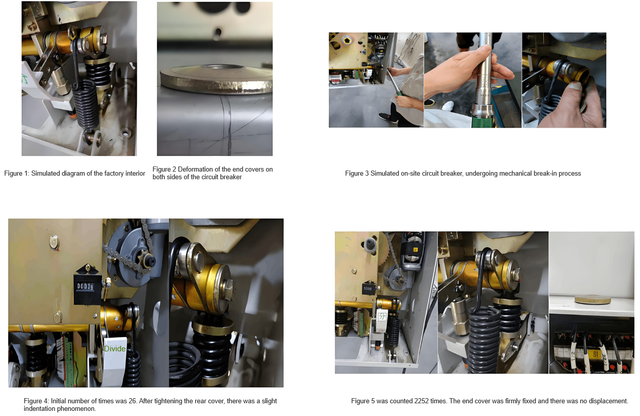
In conclusion, when the specified torque is 45 Nm, even if the axial length between the shaft sleeve and the spline shaft reaches 4 mm and the end cover is deformed and sunken, it remains well - fixed until more than 2,200 operations. Then, it proceeds to the verification of the second stage.
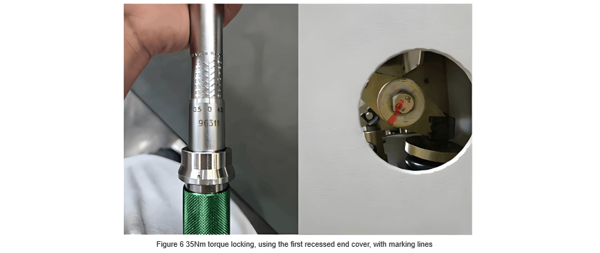
Adjust the axial length between the spline shaft on the right side of the main shaft of this simulated circuit breaker and the outer casing to create a 4 - mm gap. Use a torque wrench to tighten it with a torque of 35 Nm, and use the deformed and sunken end cover from stage 1. Mark it with a scribing line. Push it into the mechanical running - in chamber for mechanical running - in. The initial count is 2,252.In summary, when the torque is 35 Nm, even if the axial length between the shaft sleeve and the spline shaft reaches 4 mm and the end cover is deformed and sunken, it remains well - fixed until more than 1,887 operations. Then, it proceeds to the verification of the third stage (see Figure 6).
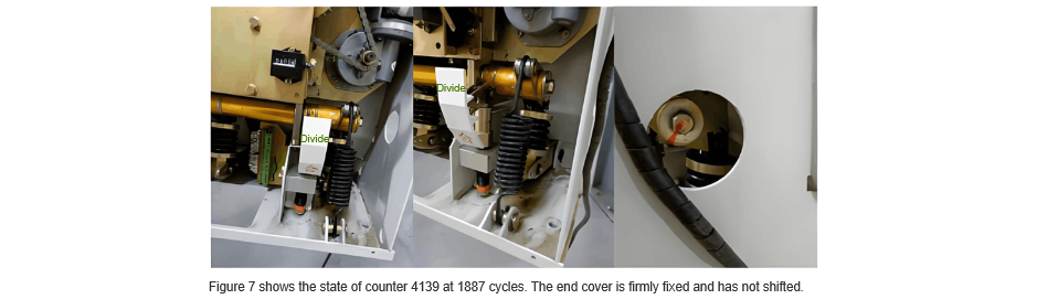
Adjust the axial length between the spline shaft on the right side of the main shaft of this simulated circuit breaker and the outer casing to create a 4 - mm gap. Use a torque wrench to tighten it with a torque of 20 Nm, and use the deformed and sunken end cover from the third stage. Mark it with a scribing line. Push it into the mechanical running - in chamber for mechanical running - in. The initial count is 4,139 (see Figure 7).
In conclusion, when the torque is 20 Nm, even if the axial length between the shaft sleeve and the spline shaft reaches 4 mm and the end cover is deformed and sunken, it remains well - fixed until more than 1,671 operations. Then, it proceeds to the verification of the fourth stage (see Figure 8 and Figure 9).
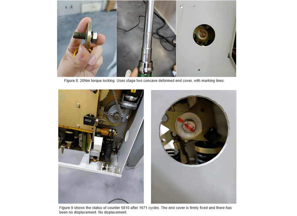
Adjust the axial length between the spline shaft on the right side of the main shaft of this simulated circuit breaker and the outer casing to create a 4 - mm gap. Use a torque wrench to tighten it with a torque of 10 Nm, and use the deformed and sunken end cover from the fourth stage. Mark it with a scribing line. Push it into the mechanical running - in chamber for mechanical running - in. The initial count is 5,810 (see Figure 10).
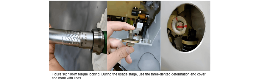
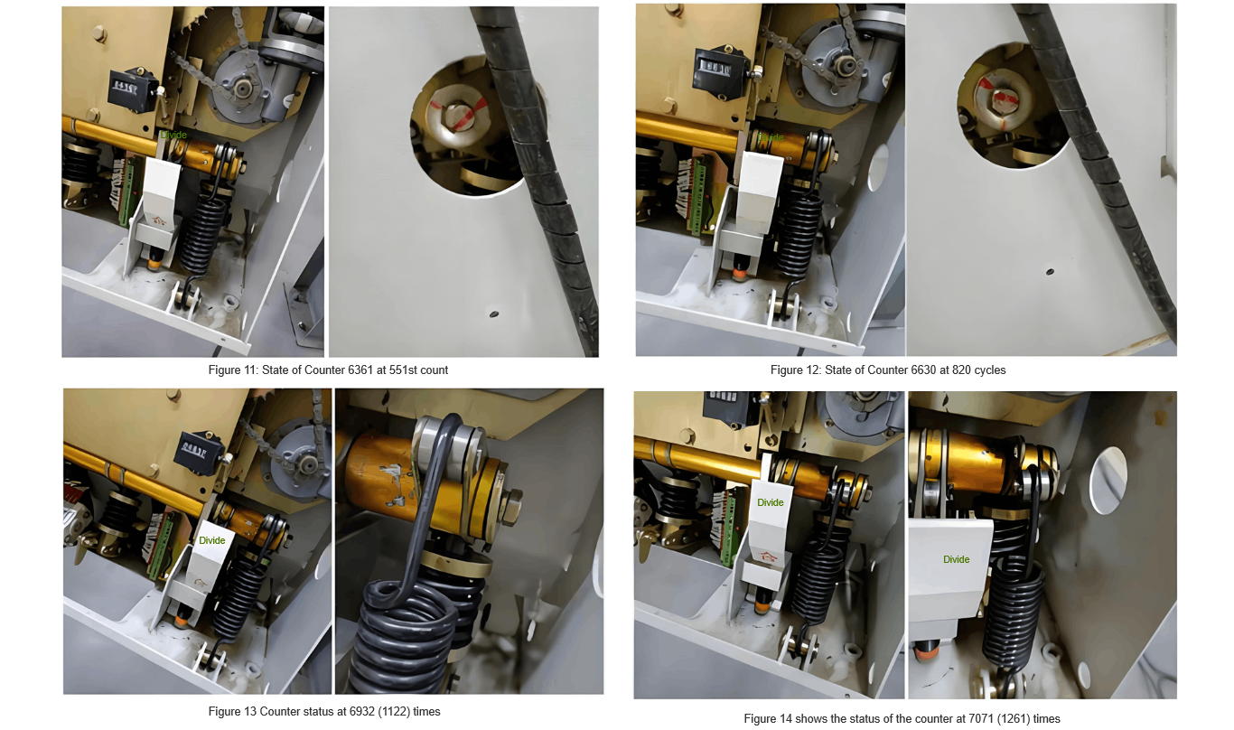
During the test process, it was found that when the counter reached 551 operations, the end cover started to rotate slightly relative to the initial position (see Figure 11); when the count increased to 820 operations, the end cover rotated slightly relative to the position at 551 operations (see Figure 12); when the count reached 1122 operations, the tripping spring was visibly loose to the naked eye (see Figure 13); when the count increased to 1261 operations, the tripping spring fell off (see Figure 14).

Hey there! I'm an electrical engineer specializing in Failure and Maintenance. I've dedicated my career to ensuring the seamless operation of electrical systems. I excel at diagnosing complex electrical failures, from malfunctioning industrial motors to glitchy power distribution networks. Using state - of - the - art diagnostic tools and my in - depth knowledge, I pinpoint issues quickly. On this platform, I'm eager to share my insights, exchange ideas, and collaborate with fellow experts. Let's work together to enhance the reliability of electrical setups.