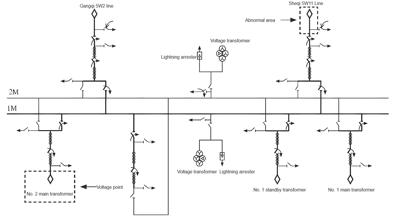
At 14:03 on December 11, 2022, an insulation handover withstand voltage test of the main circuit was carried out on the 550 kV GIS in the substation at the construction site. When testing phases B and C, the voltage was increased to 318 kV and held for 5 minutes, passing the test. When the voltage was increased to 473 kV and held for 2 minutes, a breakdown occurred. The voltage suddenly dropped to 0 V, and a relatively loud abnormal sound was heard in the substation, interrupting the test. After safety measures were taken, the insulation resistance to ground of the 1M - C phase main circuit was measured to be 400 MΩ, and that of the remaining part was 200 GΩ. It was determined that there was a fault in a certain device carried by the 1M - C phase. The wiring for the withstand voltage test and the abnormal area are shown in Figure 1. The blackened part in the figure indicates the voltage - applying range.
It can be seen from Figure 1 that the voltage - applying range includes: 6 circuit breakers carried by bus 1M, 6 bus disconnectors, 2 line - side disconnectors, 5 sets of air bushings, 1 bus disconnector of the PT carried by 1M, and 6 bus disconnectors of 2M. The voltage - applying point was set at the riser of the incoming line of Main Transformer No. 2 outdoors.
Process of Searching for Abnormal Points
The GIS has a fully - enclosed structure, with multiple independent components forming an integrated whole. The equipment associated with 1M has 83 independent gas compartments, making it rather challenging to locate abnormal points. After research, a point - by - point elimination method was adopted to narrow down the scope of the abnormal equipment.
Due to the fully - enclosed structure of the GIS, insulation can only be measured at the exposed parts, and the insulation measurement points are all on the 15 - meter - high riser seats outdoors. When measuring insulation, there are numerous restrictive factors. For example, personnel need to use a crane to get on and off, communication tools are required for liaison, and test leads need to be constantly changed during measurement. Through analysis, it was found that closing the PT disconnecting switch associated with 1M and removing the secondary ground wire of the PT would make it very convenient to use the PT as an insulation measurement point, allowing inspectors to communicate in real - time without relying on communication tools.
All the disconnecting switches connected to GIS 1M were opened, and all the circuit breakers were closed. Then, starting from the interval at the voltage - applying point, the disconnecting switches connected to 1M (excluding the 1M VT disconnecting switch) were closed one by one, and insulation was measured each time a disconnecting switch was closed. Eventually, in the outgoing line interval 5W11 of the 1M - C bus, the insulation of the main circuit was measured to be 400 MΩ. Further opening the circuit breaker of this interval, the abnormal point was finally determined to be in the area from the line - side disconnecting switch of this circuit breaker to the outdoor GIS bushing.
The abnormal area in Figure 1 was isolated, and a second voltage application was carried out on the non - abnormal parts according to the main insulation withstand voltage test procedure. The results showed compliance. Power - frequency withstand voltage tests were conducted on the remaining equipment, all of which passed smoothly.
Handling of Abnormal Points
There were 5 independent gas compartments in the abnormal area. To accurately locate the abnormal point, it was necessary to open each gas compartment one by one for inspection.Since the SF₆ gas inside the GIS became toxic after the test, on December 12, 2022, after the gas was recovered and the equipment was disassembled for inspection, it was found that the supporting insulator of the three - way busbar at the lower section of the vertical busbar in the 02 - 5 gas compartment of the 1M - C busbar was fractured. The busbar conductor, casing, and adjacent insulators all met the product technical requirements.
The manufacturer replaced the abnormal insulator on December 13, reinstalled the busbar, and completed gas treatment, leak detection, moisture measurement, and main - circuit resistance measurement. After the results were found to be qualified, on December 14, a power - frequency withstand voltage test was carried out again using the above - mentioned test wiring method and following the main - circuit insulation withstand voltage test procedure. The test results were qualified (592 kV held for 1 minute).
Analysis of the Causes of Supporting Insulator Fracture
There are a total of 145 supporting insulators in the GIS. Whether the fractured supporting insulator is an isolated case or part of a batch - wide problem is of crucial importance for the safe and reliable commissioning of the step - up substation. Therefore, to identify the root cause of the fault insulator's fracture, investigations are carried out from the following aspects.
Inspection of Busbar On - site Assembly Quality
The CX1 - 1C (factory number, the same below) busbar was assembled on - site on December 3, 2022. During the assembly process, the on - site representative of the manufacturer verified each item against the "On - site Docking Confirmation Operation Item Card". The owner and the supervisor witnessed the process jointly, and assembly could proceed only after the three parties completed the signing formalities. After the assembly was completed, on - site verification tests such as gas moisture content, leak detection, and loop resistance were carried out. This basically rules out the possibility that the insulator fracture was caused by on - site assembly quality, process, and other factors.
Inspection of the Material Compliance of Supporting Insulators for Busbars
The fractured supporting insulator has a factory - out number of Z220704 - 1G1, which was manufactured by a subsidiary company of the manufacturer in July 2022. Before leaving the factory, this supporting insulator underwent inspections and tests including visual inspection, dimensional measurement, vitrification temperature testing, X - ray flaw detection, and electrical testing, all of which showed compliance.
The factory - out inspection reports and incoming - inspection records of the insulators indicate that both the factory - out and incoming - inspection results meet the requirements.
Inspection of Busbar Manufacturing History
An inquiry into the assembly history of the CX1 - 1C busbar unit shows that the manufacturer started production and assembly on September 20, 2022, and completed the work on October 12, 2022. The records in the assembly history table indicate that both the internal and external assembly processes met the technical requirements and process standards specified in the drawings, with no abnormalities found. Therefore, it can be excluded that the processes listed in the manufacturing history table caused the fracture of the supporting insulator.
Inspection of Busbar Factory - out Tests
The CX1 - 1C busbar underwent lightning impulse, power - frequency withstand voltage, and partial discharge tests in the manufacturer's factory on October 6, 2022, all of which were passed on the first attempt, and the test results were qualified. This indicates that the busbar and insulators were normal when they left the factory.
Inspection of Abnormal Supporting Insulators
Inspections are carried out from aspects such as the failure nature of the abnormal supporting insulators and verification tests (including dimensional inspection, flaw detection, material analysis, etc.).
Failure Nature
Analysis of the surface discharge path of this insulator shows that there is an appearance of through - damage in the insulating part between the high - voltage electrode and the low - voltage electrode. Generally, the through - damage of an insulator occurs due to the presence of certain defects inside the insulating part, or due to additional mechanical stress, which causes cracks inside the insulating part, and then through - breakdown occurs along the cracks.
Verification Tests
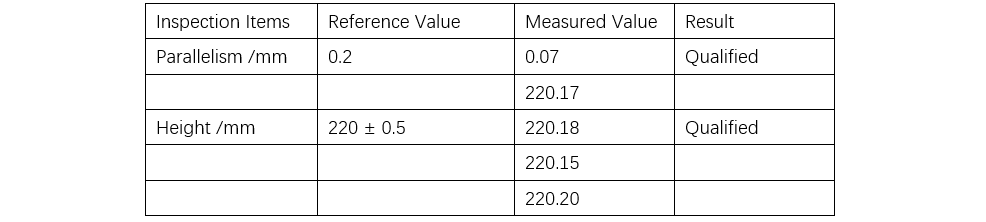
Dimensional re - inspection. The dimensional re - inspection of the abnormal supporting insulator was qualified. The re - inspection results are shown in Table 1.
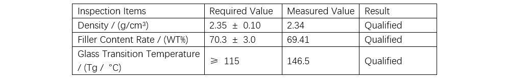
X - ray flaw detection. X - ray flaw detection was carried out on the abnormal supporting insulator, and no external defects other than fracture cracks were found.Resin material re - inspection. Samples were taken from the abnormal specimens for re - inspection of density, filler content rate, and glass transition temperature, and the results were qualified. The resin material detection results are shown in Table 2.
Re - inspection of the resin - to - electrode bonding interface. The non - discharged area of the insulator was cut, and the resin - to - metal bonding surface of the insulator was dyed for flaw detection. Except for the local slight penetration of the coloring agent at the fracture, the rest of the area was normal, proving that there were no defects inside the resin and that the resin was well - bonded to the electrode.
Re - inspection of resin melting. After the resin of the abnormal supporting insulator was melted at high temperature, the electrode was re - inspected. There was local abnormal deformation at the position of the discharge point on the arc - shaped surface of the high - voltage electrode. In conclusion, during the manufacturing process of the supporting insulator, improper operation caused abnormal deformation of the arc - shaped surface of the high - voltage electrode. Since the deformation was minor, the operators failed to detect it in a timely manner, allowing defective components to enter the next process and eventually leading to the pouring of the insulator.
This failure was caused by non - standard operation of the operators, which led to abnormal deformation of the electrode and subsequent fracture of the insulator. The structure of this supporting insulator is an insulation structure that the manufacturer has been using. Since 2003, more than 36,000 insulators have been manufactured and are operating reliably in the field. Therefore, the fracture of this supporting insulator is an isolated case.
Simulation Verification
For safety reasons, simulation verification was carried out on the busbar with this insulator structure.Voltage application: The central conductor and the high - voltage electrode of the insulator are at 1675 kV, while the casing, support base, and low - voltage electrode of the insulator are at 0 potential.
Judgment criteria: Under the minimum functional gas pressure of 0.45 MPa, the surface - flashover electric field strength of the insulator should not exceed 12 kV/mm, and the electric field strength of the high - voltage electrode of the insulator should not exceed 50 kV/mm.
The simulation results show that the maximum surface - flashover electric field strength of the insulator is 10.5 kV/mm, which is less than 12 kV/mm, and the result is qualified. The maximum electric field strength on the surface of the high - voltage electrode is 21.2 kV/mm. Converted to the condition of a power - frequency voltage of 318 kV, the maximum electric field strength is 40.2 kV/cm, which is less than 50 kV/cm, and the result is also qualified.
The 550 kV GIS of the 500 kV step - up substation was successfully energized for the first time on December 28, 2022. Unit 2 was connected to the grid for the first time on November 29, 2023. All equipment in the substation has withstood the pressure test and is operating normally.
Conclusion
For important high - voltage equipment of 110 kV and above, it is necessary to strictly follow the relevant requirements of DL/T 586—2008 "Technical Guidelines for Supervision of Power Equipment Manufacturing" to strengthen the factory - based supervision of equipment and control the manufacturing quality of equipment from the source. GIS manufacturers must enhance their quality control awareness, comprehensively sort out the quality - related risk points at each post, and improve documents such as operation specifications, operation standards, and operation procedures for product assembly at all voltage levels. Comprehensive control should be carried out over links such as component procurement, product design, component processing technology, incoming inspection, product assembly, testing, and on - site installation to ensure the safety, stability, and reliability of products.