Intelligent Diagnosis and Analysis of Mechanical Failures in High-Voltage Isolating Switches

Felix Spark
05/29/2025
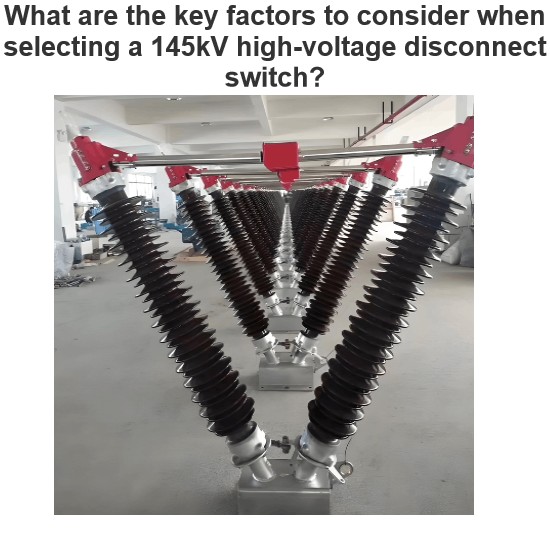
In modern power systems, high - voltage disconnect switches play a crucial role. They ensure the safe isolation of electrical equipment or lines during maintenance and the reliability during normal operation. Mechanical failures of high - voltage disconnect switches, such as poor contact, actuator failure, or structural component fatigue, can severely impact the stability and safety of the entire power system.Traditional fault - detection methods rely on regular maintenance and manual inspections.
These methods are not only time - consuming and labor - intensive but also prone to missing the optimal intervention time in the early stages of a fault. With the continuous progress of technology, intelligent diagnostic techniques have emerged, offering a more efficient and accurate solution for fault monitoring and diagnosis.
Intelligent diagnostic methods, such as sensor - based data collection, data processing and analysis, drive - motor current signal analysis, and resistive strain measurement, can identify abnormal behaviors of high - voltage disconnect switches in real - time, predict potential faults, and guide maintenance decisions. This significantly enhances the reliability and operational efficiency of the power system.
1 Common Types of Mechanical Failures in High - Voltage Disconnect Switches
1.1 Poor Contact Failure
1.1 Poor Contact Failure
Poor contact is mainly caused by contact - surface oxidation, insufficient contact pressure, or a reduced contact area. This type of failure usually leads to an increase in resistance, affecting the conductivity of the high - voltage disconnect switch. Due to poor contact, more heat is generated when current passes through the contact points. This not only accelerates the wear of the contact points but also causes more serious thermal - effect problems, such as welding failure or local overheating.
Poor contact can also cause voltage instability, affecting the voltage quality of the power system. Persistent poor - contact issues can easily lead to a decline in the insulation performance of the high - voltage disconnect switch, increasing the operational safety risks of the system. Therefore, promptly detecting and properly addressing poor - contact problems in high - voltage disconnect switches is essential for ensuring the stable and safe operation of the power system.
1.2 Actuator Failure
Actuator failure is a significant issue affecting the performance of high - voltage disconnect switches. This type of failure encompasses mechanical wear, insufficient lubrication, and component aging. Mechanical wear typically refers to the damage of driving components such as bearings and gears under long - term repetitive operations. Insufficient lubrication increases friction, accelerating the wear rate of mechanical parts and reducing the operational efficiency of the actuator.
As the service time increases, various components of the actuator lose their original properties or deform due to material aging, thereby affecting the reliability and safety of the entire high - voltage disconnect switch operation. If these failures are not detected and addressed in a timely manner, it can lead to incorrect operation of the high - voltage disconnect switch, and in severe cases, even endanger the stable operation of the entire power system.
1.3 Structural Component Fatigue and Damage Failure
Structural component fatigue and damage failures usually occur under the influence of long - term mechanical stress and environmental factors. Structural components such as pillars, connecting rods, and bearings gradually experience material fatigue under the action of long - term mechanical stress, especially during frequent opening and closing operations. Over time, these stresses accumulate within the material, leading to the generation and propagation of micro - cracks, which eventually develop into significant mechanical damage.
In addition, environmental factors such as temperature changes, humidity, and corrosive environments can accelerate the fatigue rate of structural components, affecting their mechanical properties and service life. Structural component fatigue and damage failures not only affect the normal function of high - voltage disconnect switches but also pose a threat to the overall stability of the power system.
2 Intelligent Diagnosis Methods for Mechanical Failures of High - Voltage Disconnect Switches
2.1 Sensors and Data Collection
2.1 Sensors and Data Collection
Sensors play a vital role in the mechanical fault diagnosis of high - voltage disconnect switches. They are mainly responsible for capturing key physical parameters during equipment operation, such as vibration, sound, temperature, and current. For high - voltage disconnect switches, the main sensors used include vibration sensors, acoustic emission sensors, and current and voltage sensors.
Vibration sensors are used to detect the vibration frequency and amplitude generated by equipment components during operation. By analyzing vibration data, it is possible to predict equipment wear and existing faults. Generally, the vibration frequency of a normally operating high - voltage disconnect switch should be within the standard range (usually, the threshold is set to more than 10 times the operating frequency). If it exceeds this range, it may indicate an anomaly. A schematic diagram of a vibration sensor is shown in Figure 1.
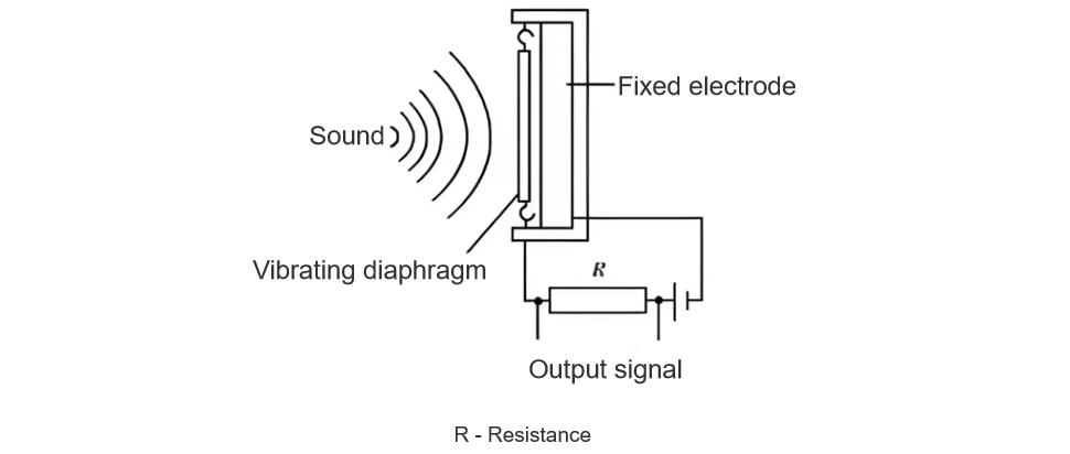
Acoustic emission sensors capture sound based on high - frequency sound waves generated by material or structural defects. During the operation of a high - voltage disconnect switch, if there are cracks or looseness, acoustic emission sensors can promptly capture the sound fluctuations caused by these minor deformations or ruptures. The principle of an acoustic emission sensor is shown in Figure 2.
Current and voltage sensors mainly monitor changes in the current and voltage levels passing through the high - voltage disconnect switch. Abnormal current or voltage readings from these sensors usually indicate problems with electrical connections or functionality.
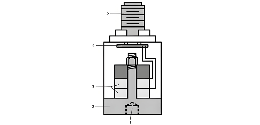
1 - Bolt holes; 2 - Foundation;3 - Piezoelectric crystals;4 - Electronic Amplifier;5 - Terminal Connector
In terms of data collection, the main task is to convert the data collected by sensors into usable information. A data collection system typically consists of the following three aspects:
- Data Acquisition Unit (DAU). The DAU is mainly responsible for receiving analog signals from various sensors and converting these analog signals into digital signals. The DAU ensures that data is collected at an appropriate rate (usually with a response time in the millisecond range) and with a certain precision (usually reaching 16 bits or higher) to meet subsequent processing requirements.
- Data Transmission. The collected data is transmitted to a central processing server through a stable communication network. This step often relies on wireless communication technologies such as Wi - Fi or 4G/5G networks, which can further increase the speed and efficiency of data transmission and reduce the complexity and cost of wiring.
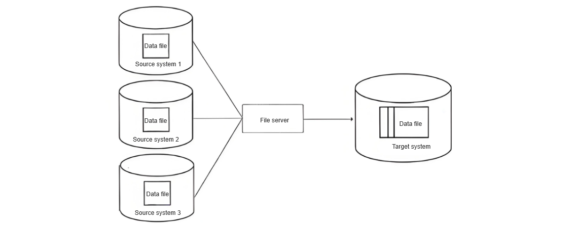
- Data Storage and Management. After successful data transmission, effective data storage and management must be carried out on a server or in the cloud to establish a more complete database. Data storage needs to support fast access and large - scale data analysis, so high - performance databases are required to achieve data query and retrieval. A schematic diagram of database establishment is shown in Figure 3.
Through sensors and data collection, real - time monitoring of the operating status and performance indicators of equipment can promptly detect potential defects, providing a necessary basis for intelligent diagnosis of mechanical failures, preventing the occurrence of failures, and ensuring the stable operation of the power system.
2.2 Data Processing and Analysis
2.2.1 Time - Frequency Analysis
2.2.1 Time - Frequency Analysis
Time - frequency analysis is an efficient data - processing method that can transform signals from the time domain to the frequency domain, thereby revealing the internal characteristics and changing trends of signals. Commonly used time - frequency analysis methods include Short - Time Fourier Transform (STFT), wavelet transform, and Wigner - Ville distribution.
STFT performs a local Fourier transform on the signal through a window of fixed size, making it suitable for analyzing signals whose frequencies change slowly over time. For example, when monitoring the actuator, STFT can effectively identify frequency drifts caused by friction or structural looseness.
The wavelet transform can provide windows of variable size, making it suitable for processing signals with instantaneous mutation characteristics. By adjusting the mother wavelet function, precise identification of abnormal vibrations within a specific frequency band can be achieved.
As an advanced time - frequency analysis tool, the Wigner - Ville distribution, despite generating cross - term interference, offers a more refined analysis of the signal's time and frequency, making it particularly suitable for fault detection in complex signal environments.
In practical applications, combining the above - mentioned time - frequency analysis methods with the original data measured by sensors can accurately monitor and diagnose the operating conditions of high - voltage disconnect switches. Under normal operating conditions, the frequency range of high - voltage disconnect switches can generally be maintained at 50 - 100 Hz; while in the case of poor contact, structural component fatigue, and damage failures, the frequency of high - voltage disconnect switches will shift significantly or new frequency components will appear.
2.2.2 Machine Learning and Pattern Recognition
First, after data collection, through a pre - processing stage such as noise elimination and feature extraction, input data is prepared for machine - learning algorithms. The data includes frequency components of vibration signals, waveform characteristics of electrical parameters, etc.
Second, supervised learning algorithms such as Support Vector Machines (SVM) and Random Forest can be used to classify the data obtained from sensors. These algorithms are trained to identify different types of fault patterns, such as the unique signal patterns caused by poor contact or actuator failures. In practical applications, thousands of data points are input into the algorithms for training to ensure that they can accurately identify fault states.
Finally, deep - learning techniques, especially Convolutional Neural Networks (CNN), are used for complex pattern recognition. Deep - learning techniques can extract useful information from large - scale multi - dimensional data through their automatic feature - learning capabilities, improving the accuracy of diagnosis. For example, in a specific CNN model, several convolutional layers and pooling layers are designed to process the collected video image data to identify typical fault features.
2.3 Drive Motor Current Signal Analysis
Real - time monitoring and analysis of the current signals generated during the operation of the drive motor can predict and diagnose potential mechanical failures. Drive motor current signal analysis generally focuses on detecting small changes in the current signal to determine the anomalies or wear of mechanical components.
If there are failures in the mechanical components of the high - voltage disconnect switch, such as bearing damage, gear wear, or imbalance, it will indirectly affect the load of the drive motor, thereby causing specific pattern variations in its current signal.
In terms of data analysis, a current sensor is used to record the current waveform under normal operating conditions around the motor's power - supply coil. The sampling frequency is usually set above 20 kHz to capture detailed information and ensure high - precision data parsing.
In terms of feature extraction, the Fourier transform is used to convert the time - domain current signal into a frequency - domain signal, which helps to identify harmonic anomalies caused by mechanical failures. For example, under fault - free conditions, the drive motor current signal mainly contains the fundamental frequency and its integer - multiple harmonics. If there is a fault, such as bearing failure, new peaks will be observed at specific frequencies.
In subsequent data processing, statistical methods can be used to analyze the extracted frequencies. For example, calculate the amplitude changes of each frequency point, and train a fault - identification model using a machine - learning algorithm. The input of the algorithm is the frequency characteristics of the current signal, and the output is the prediction of the fault type and severity.
By analyzing the current signal, the deviation of the current signal can be quantified. For example, in the initial stage of bearing failure, the amplitude of the current harmonic can increase by 5 - 10 A, while in the case of gear wear, the amplitude of the relevant harmonic can increase by 3 - 8 A. This enables the maintenance team to accurately determine the equipment status and plan maintenance work, thereby avoiding large - scale power outages caused by failures.
2.4 Application of Resistance Strain Measurement Technology
Resistance strain measurement technology can be used to monitor the structural stress and deformation of high - voltage disconnect switches. This technology is realized through resistance strain gauges installed on key components.
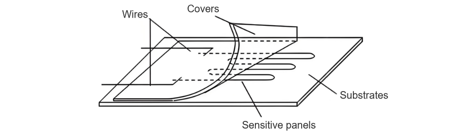
A resistance strain gauge is a sensor that converts mechanical deformation into an electrical signal. Its working principle is based on the property that the resistance value of a metal conductor changes when it is deformed under force. A schematic diagram of the resistance strain gauge structure is shown in Figure 4.
When selecting resistance strain gauges, high - precision metal foil resistance strain gauges can be chosen. These gauges have good linear characteristics and stable temperature response, and are usually installed at the positions where the high - voltage disconnect switch is most stressed and most prone to fatigue, such as the contact arm and the rotating shaft.
After the selection and installation of the resistance strain gauges are completed, the gauges are required to be connected to the data collection system through wires. The data collection system is responsible for recording the resistance changes transmitted from the resistance strain gauges and converting them into voltage signals for reading. The data collection system needs to have a high - speed sampling rate and high resolution to ensure that it can capture the rapid strain changes generated during the operation of the high - voltage disconnect switch. The sampling rate used is usually in the kilohertz range, and the resolution reaches the millivolt level.
Appropriate software is used to process the collected voltage signals. First, filtering is performed to remove possible noise interference, and then mathematical algorithms such as the Fast Fourier Transform (FFT) are used to analyze the signal spectrum and extract strain data. The strain data can be converted to obtain the actual stress state of the corresponding component.
The measured strain data is compared with the pre - established stress model of the high - voltage disconnect switch to evaluate the current health status of the equipment. When the monitored stress exceeds the design threshold, the data collection system will automatically issue a warning signal to remind the operation and maintenance personnel to conduct inspections or maintenance.
3 Conclusion
This article has in - depth explored the common types of mechanical failures of high - voltage disconnect switches and their intelligent diagnosis methods. Using intelligent diagnosis methods for mechanical failures of high - voltage disconnect switches can not only improve the reliability of equipment operation but also significantly reduce maintenance costs and optimize the maintenance decision - making process.
With the progress of science and technology and the increasing maturity of data analysis technology, relevant personnel need to increase research investment to improve the intelligent diagnosis level of mechanical failures of high - voltage disconnect switches, providing strong support for the stable operation of the power system.
Hey there! I'm an electrical engineer specializing in Failure and Maintenance. I've dedicated my career to ensuring the seamless operation of electrical systems. I excel at diagnosing complex electrical failures, from malfunctioning industrial motors to glitchy power distribution networks. Using state - of - the - art diagnostic tools and my in - depth knowledge, I pinpoint issues quickly. On this platform, I'm eager to share my insights, exchange ideas, and collaborate with fellow experts. Let's work together to enhance the reliability of electrical setups.