Parallel Magnetic Circuit

Edwiin
05/28/2025

Definition of Parallel Magnetic Circuit
A parallel magnetic circuit is defined as a magnetic pathway with two or more branches for magnetic flux, analogous to a parallel electric circuit. Such circuits feature multiple flux paths with varying cross-sectional areas and materials, each potentially composed of different magnetic components.
Parallel Magnetic Circuit Analysis
The figure above depicts a parallel magnetic circuit, where a current-carrying coil is wound around the central limb AB. This coil generates a magnetic flux φ₁ in the central limb, which travels upward and splits into two parallel paths: ADCB and AFEB. The path ADCB conducts flux φ₂, while AFEB carries flux φ₃. As evident from the circuit:
Parallel Magnetic Circuit Characteristics
The two magnetic paths ADCB and AFEB form a parallel magnetic circuit, where the ampere-turns (ATs) required for the entire parallel circuit equal the ampere-turns needed for any single branch.
As is known, reluctance is defined as:
Parallel Magnetic Circuit MMF Calculation
Thus, the total magnetomotive force (MMF) or ampere-turns required for a parallel magnetic circuit equals the MMF of any single parallel path, as all branches experience the same applied MMF.
Incorrect Notation Clarification:
The total MMF is not the sum of individual paths (a common misconception). Instead, since parallel magnetic paths share the same applied MMF, the correct relation is:

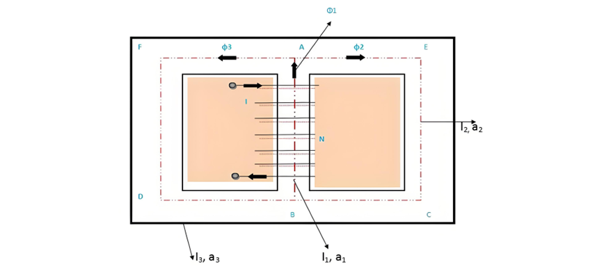
Total MMF = MMF for path BA = MMF for path ADCB = MMF for path AFEB

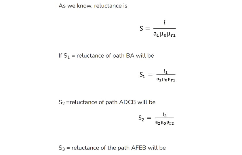
Where φ1. Φ2, φ3 is the flux and S1, S2, S3 are the reluctances of the parallel path BA, ADCB and AFEB respectively.

Edwiin

Inquiry
Download
Experts Electrical is dedicated to serving the personnel in the global power industry.
Join Experts Electrical, not only can you discover power equipment and power knowledge, but also canhnd like - minded friends!